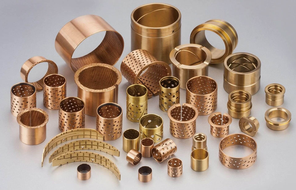
Domov / Produkt / JDB pevné mlužujúce ložisko / JGBF Brass Oilless Ejector Flanged Guide Bearings Bushings
veľkoobchod JGBF Brass Oilless Ejector Flanged Guide Bearings Bushings

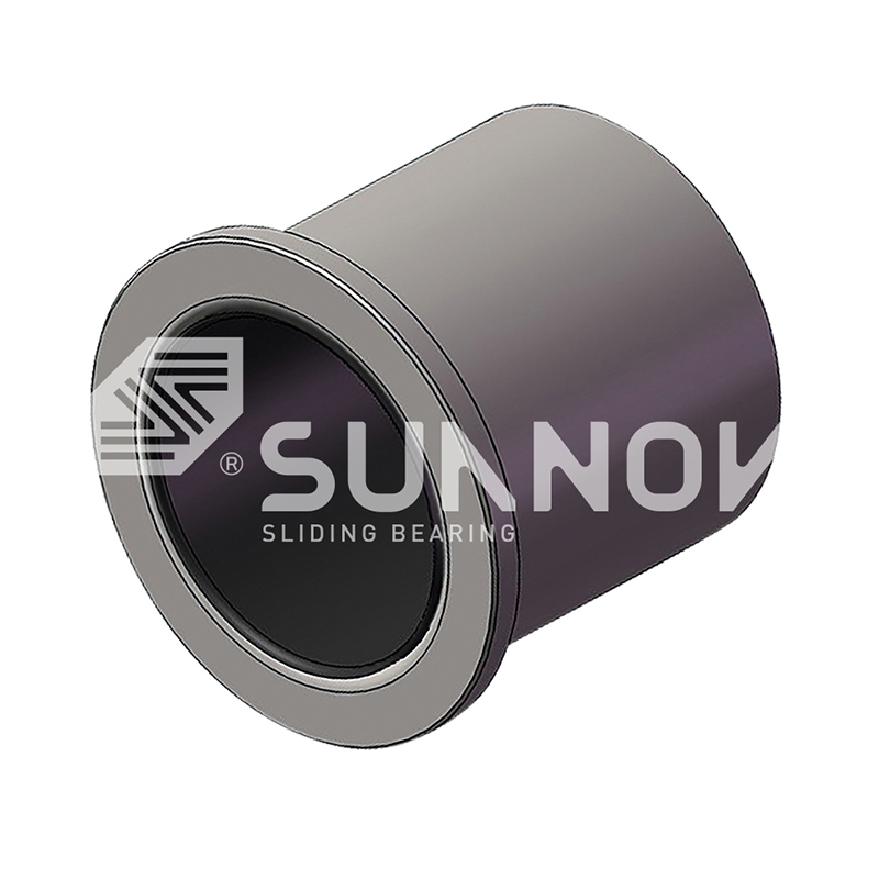
JGBF Brass Oilless Ejector Flanged Guide Bearings Bushings

Popis produktu:

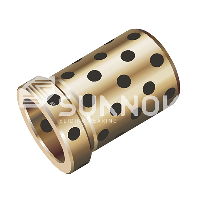
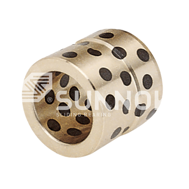
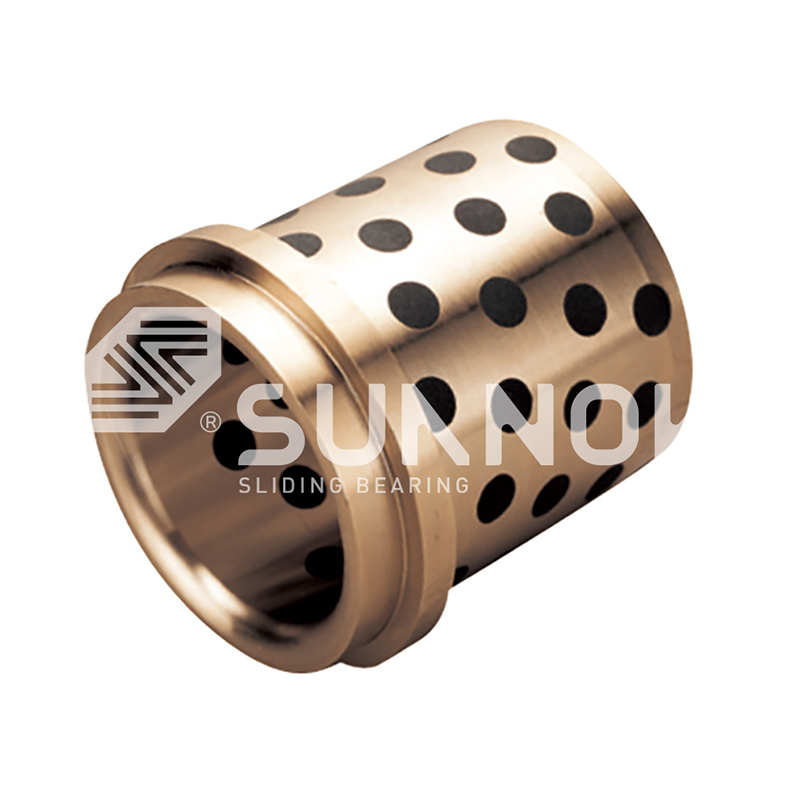
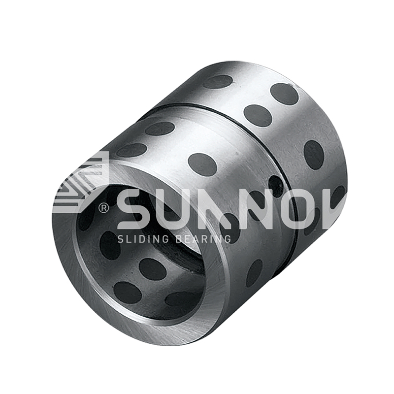
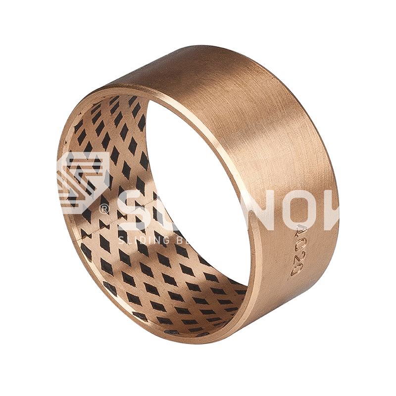
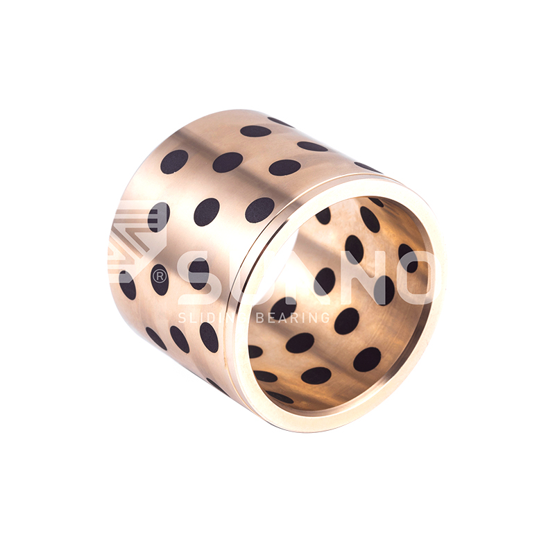
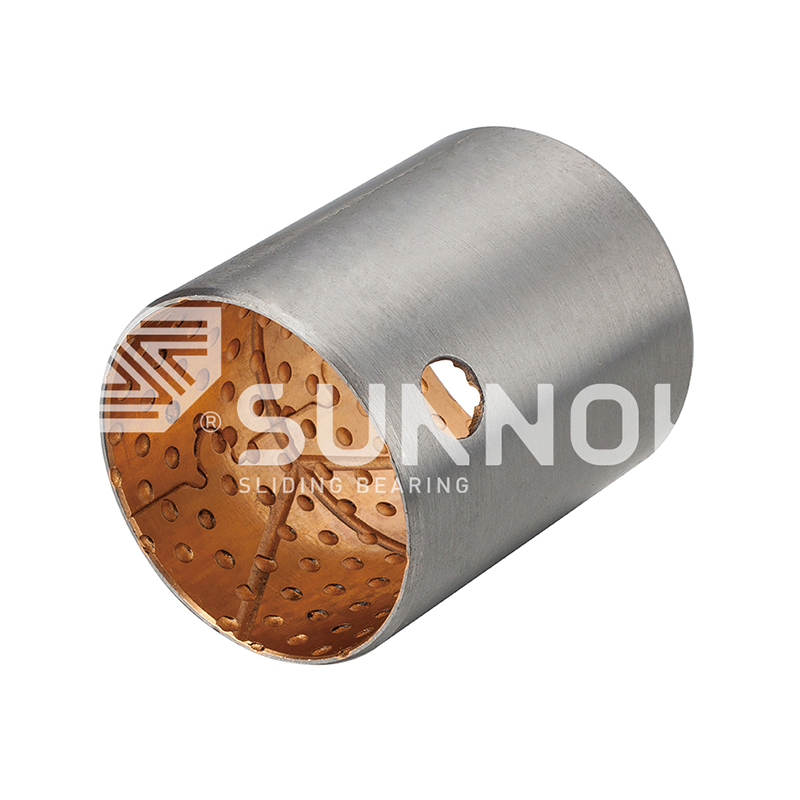
JGBF Brass Oilless Ejector Flanged Guide Bearings Bushings Brass is used as the base material and graphite solid lubricant is embedded in it, which has self-lubricating properties. The bearings have a low friction coefficient (0.05-0.12) and can operate stably under high load and high temperature environments without external lubrication. They have strong wear resistance and long service life. JGBF bearings are corrosion-resistant and suitable for a variety of harsh working conditions. Applications include machinery manufacturing, automobiles, construction, port machinery, agriculture, medical treatment and wind energy, and are widely used in equipment that requires high precision, high load capacity and maintenance-free operation. There are a variety of standard sizes to adapt to a variety of mechanical equipment.

Popis produktu

Standard No. d L d  G6 D  m6 D1 T L1
JGBF-12×19 12  19  12  +0.016
+0.006
18  +0.018
+0.007
25  19 
JGBF-12×24 24
29
24 
JGBF-12×29 29 
JGBF-12×34 34  34 
JGBF-16×19 16  19  16  25  +0.025
+0.009
30  19 
JGBF-16×24 24  24 
JGBF-16×29 29  29 
JGBF-16×34 34  30 
JGBF-16×39 39
49
30 
JGBF-16×49 30 
JGBF-20×24 20  24  20  +0.020
+0.007
30  35  24 
JGBF-20×29 29  29 
JGBF-20×34 34  34 
JGBF-20×39 39  39 
JGBF-20×49 49 40 
JGBF-20×59 59 40 
JGBF-25×24 25  24 25  35  +0.025
+0.009
40  24 
JGBF-25×29 29 29 
JGBF-25X34 34 34 
JGBF-25X39 39  39 
JGBF-25×49 49  49 
JGBF-25×59 59 50 
JGBF-25×69 69 50 
JGBF-30×29 30  29 30  42 47  10  29 
JGBF-30×34 34 34 
JGBF-30×39 39  39 
JGBF-30×49 49  49 
JGBF-30×59 59  59 
JGBF-30×69 69  60 
JGBF-30×79 79  60 
JGBF-35×39 35  39  35


+0.025
+0.009
48 +0.025
+0.009
54  10 39 
JGBF-35×49 49  49 
JGBF-35×59 59  59 
JGBF-35×69 69  69 
JGBF-35×79 79  70 
JGBF-35×89 89  70 
JGBF-35×99 99  70 
JGBF-40×39 40 39  40 55 +0.030
+0.011
61 39 
JGBF-40×49 49  49 
JGBF-40×59 59  59 
JGBF-40×69 69  69 
JGBF-40×79 79  79 
JGBF-40×89 89  80 
JGBF-40×99 99  80 
JGBF-40×109 109  80 
JGBF-50×49 50 49  50 70 76 12 49 
JGBF-50×59 59  59 
JGBF-50×69 69  69 
JGBF-50×79 79  79 
JGBF-50×89 89  89 
JGBF-50×99 99  90 
JGBF-50×109 109  90 
JGBF-50×119 119  90 
JGBF-60×99 60 99  60  +0.029
+0.010
80  86  15  99 
JGBF-60×109 109  109 
JGBF-60×119 119 110 
JGBF-60×129 129  110 
JGBF-60×149 149  110 

Predstavenie produktu

Flanged Ejector Guide Series

JGBF Brass Oilless Ejector Flanged Guide Bearings Bushings

300
°C
Operating Temperature
Flanged
Configuration
Integral Retention
0.18
μ
Friction at 250°C
Flanged Guide Architecture

The JGBF series combines high temperature brass substrate with an integral flange designed specifically for ejector guide applications. The flange provides positive axial location within the mold or die platen, eliminating the need for separate retaining rings or shoulder bolts. This configuration simplifies installation and ensures consistent guide positioning during thermal cycling. Graphite lubricant inserts are distributed across both the cylindrical guide bore and the flange thrust face, providing lubrication for both radial guidance and axial seating contact. The flanged design also facilitates easier removal during maintenance through access from the flange side.

Flange Diameter 1.5x OD standard
Flange Thickness 2.5mm - 5.0mm
Guide Tolerance ISO H8 at 20°C
F
Flange Retention Integral flange eliminates separate hardware, reduces assembly steps
T
Thermal Stability Special brass alloy maintains dimensional accuracy to 300°C
G
Dual Surface Lubrication Graphite on bore and flange face for combined motion lubrication
E
Ejector Pin Guidance Designed specifically for ejector pin stroke and load requirements

Flanged Design Specifications

Flange Face Flatness 0.015mm per 50mm diameter Perpendicular to bore axis
Flange OD Tolerance ISO h11 Standard clearance fit
Flange Corner Radius R1.0mm maximum Prevents stress concentration
Flange Graphite Pattern Radial insert arrangement 8 inserts on flange face

Flanged Guide Applications

  • Injection molding ejector plates with guided pins
  • Die casting ejector systems requiring axial retention
  • Hot stamping tool ejector mechanisms
  • Thermoforming mold ejector guides
  • Compression molding press ejectors
  • Automated transfer die ejector systems

Flange Integration Benefits

  • Self-aligning flange face with counterbore seat
  • Eliminates separate thrust washer components
  • Reduces assembly time by 40% compared to non-flanged
  • Provides visual confirmation of full seating during installation
  • Allows removal using pry tool without damaging housing

Flanged Configuration Comparison

Feature JGBF Flanged Standard Sleeve With Retaining Ring
Axial Retention Method Integral flange Interference fit only Separate ring
Assembly Components 1 1 2
Disassembly Access Flange side Press out from rear Ring removal required
Axial Load Capacity 45 N/mm² 25 N/mm² 35 N/mm²
Thermal Expansion Matching Optimized for steel Standard Ring dependent

Flanged Guide Size Matrix

Guide ID mm OD mm Flange OD mm Length L mm Flange Thick mm Max Pin Speed m/s
6 10 16 12, 16, 20 2.0 0.6
8 12 20 16, 20, 25 2.5 0.6
10 16 26 20, 25, 30 2.5 0.55
12 18 30 25, 30, 40 3.0 0.5
16 24 38 30, 40, 50 3.0 0.45
20 30 48 40, 50, 60 3.5 0.4
25 36 56 50, 60, 80 4.0 0.35
32 44 68 60, 80, 100 4.0 0.35
40 54 82 80, 100, 120 4.5 0.3
50 66 100 100, 120, 150 5.0 0.3
Flange thickness and diameter can be customized for specific mold platen counterbore dimensions.
Installation Sequence
1 Clean counterbore shoulder and bore. Verify depth matches flange thickness.
2 Chamfer counterbore entry at 1.5mm x 15 degrees to prevent flange edge damage.
3 Apply thin lubricant to housing bore only. Do not apply to guide bore.
4 Press using flat tool contacting flange face uniformly. Press until flange seats.
5 Verify flange flushness with housing surface. Tolerance ±0.05mm.
Frequently Asked Questions
Can the flange face handle thrust loads Yes. Flange face supports axial loads up to 45 N/mm². Graphite inserts on flange provide lubrication during axial contact.
What is the recommended counterbore depth Counterbore depth should equal flange thickness plus 0.05mm clearance for thermal expansion at operating temperature.
How to remove a JGBF bearing Use a pry tool between flange edge and housing. Do not pry against the guide bore or graphite inserts.
Flange eccentricity tolerance Flange OD concentricity to guide ID maintained within 0.05mm TIR for standard production.
Flange Surface Finish Ra 0.8 µm
Bore Surface Finish Ra 0.4 µm
Material Grade CuSn8 High Temp
Graphite Coverage 22% bore / 18% flange
Zhejiang Shuangnuo Technology Co., Ltd.
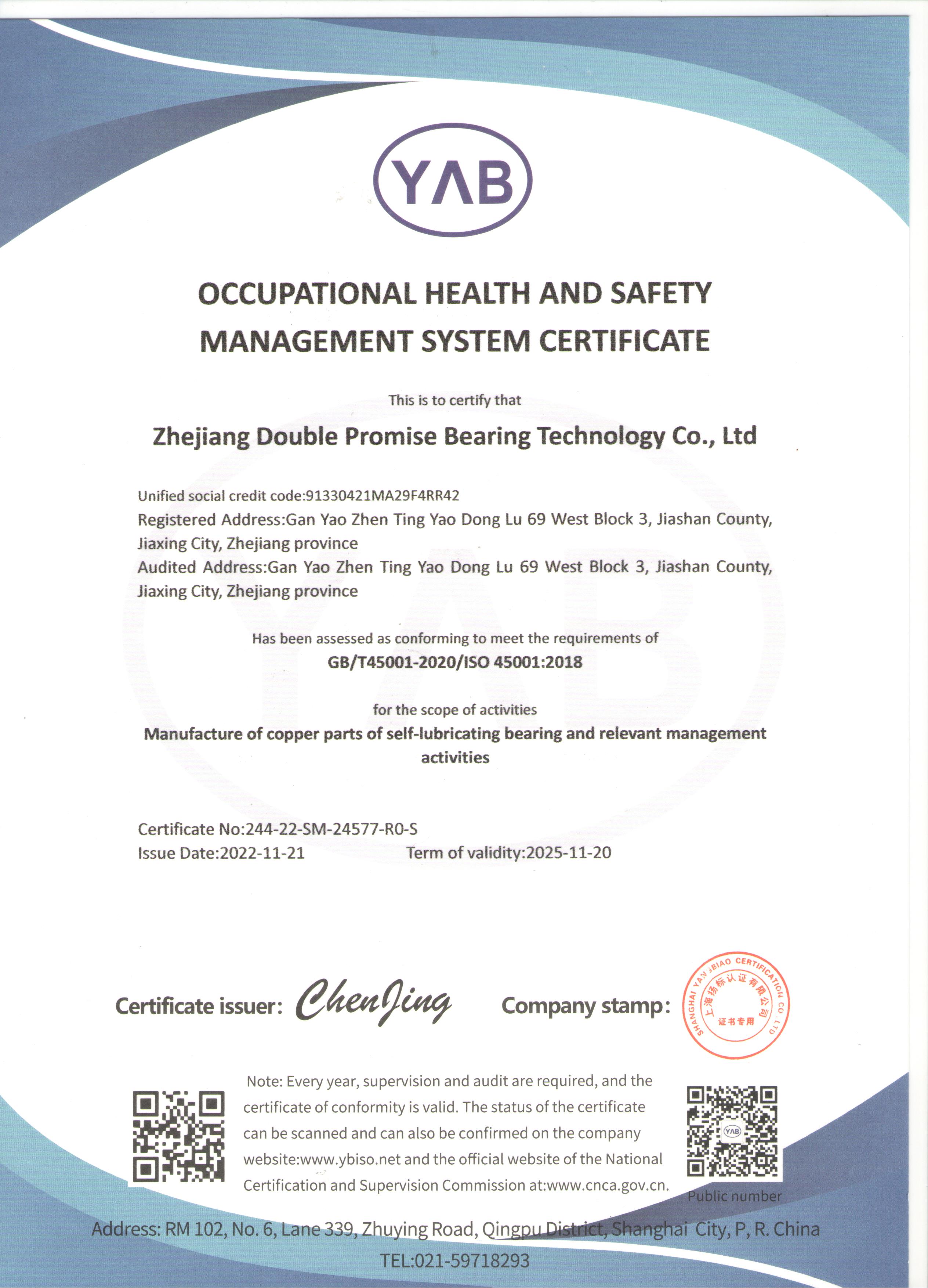
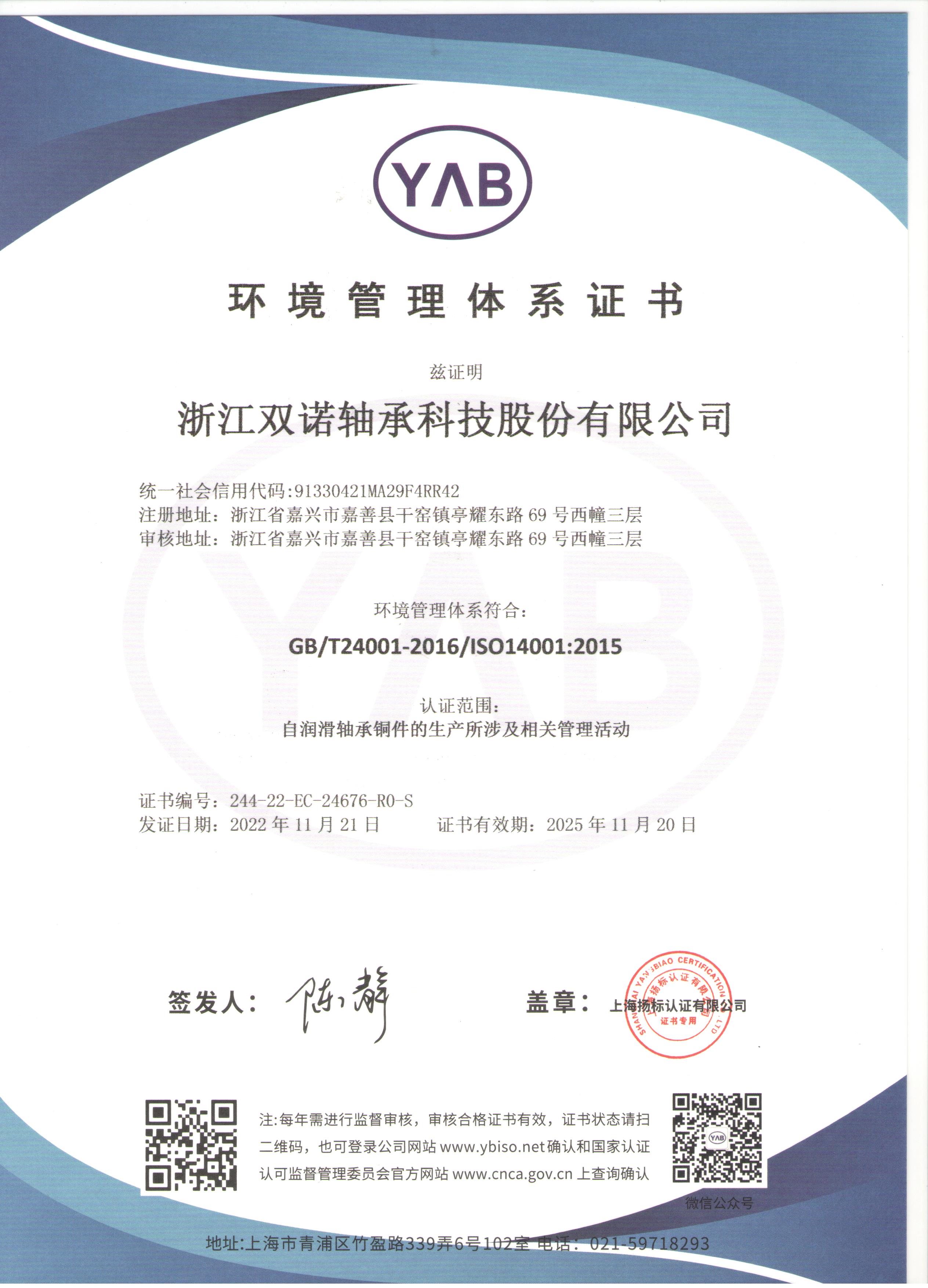
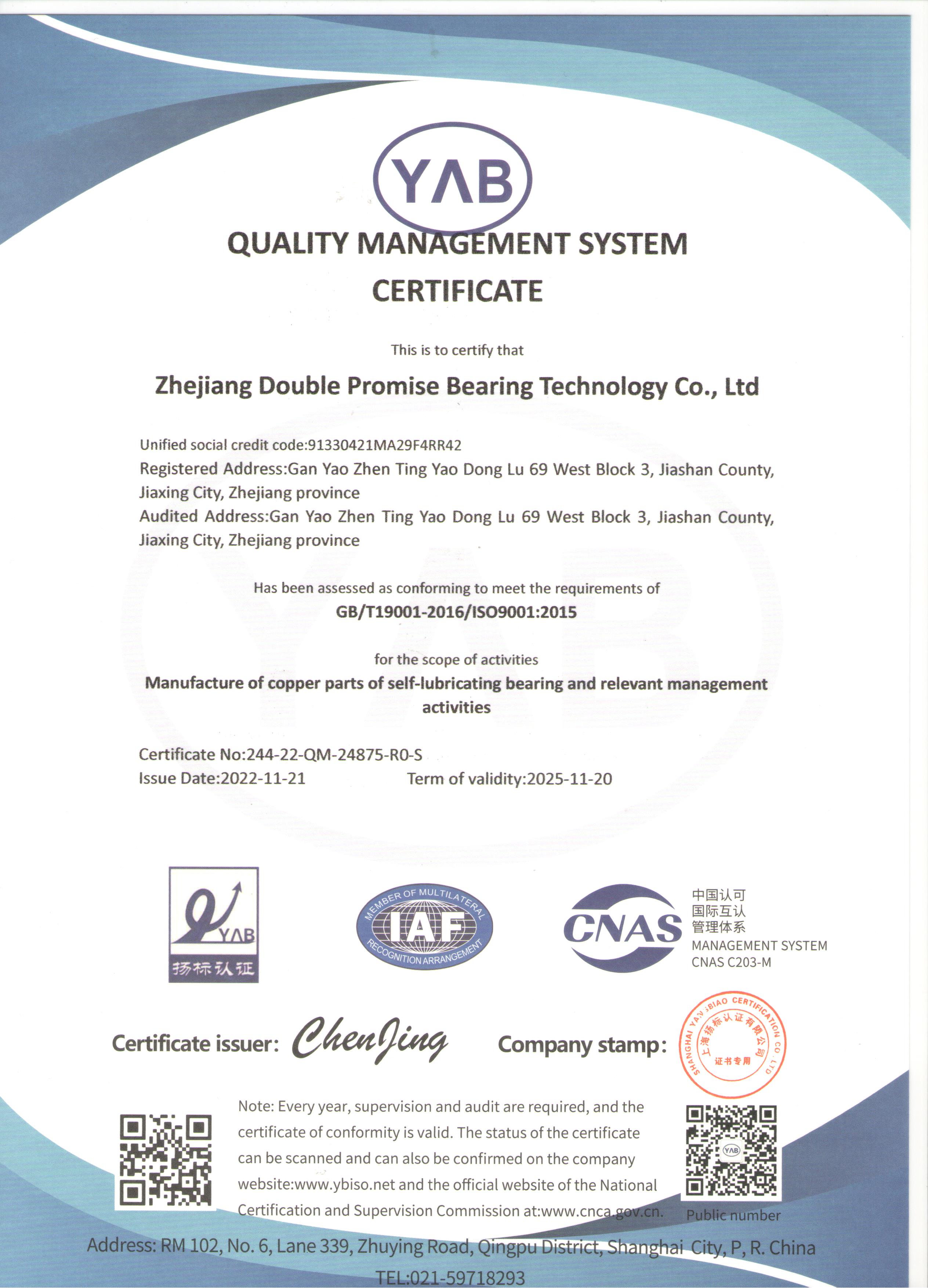
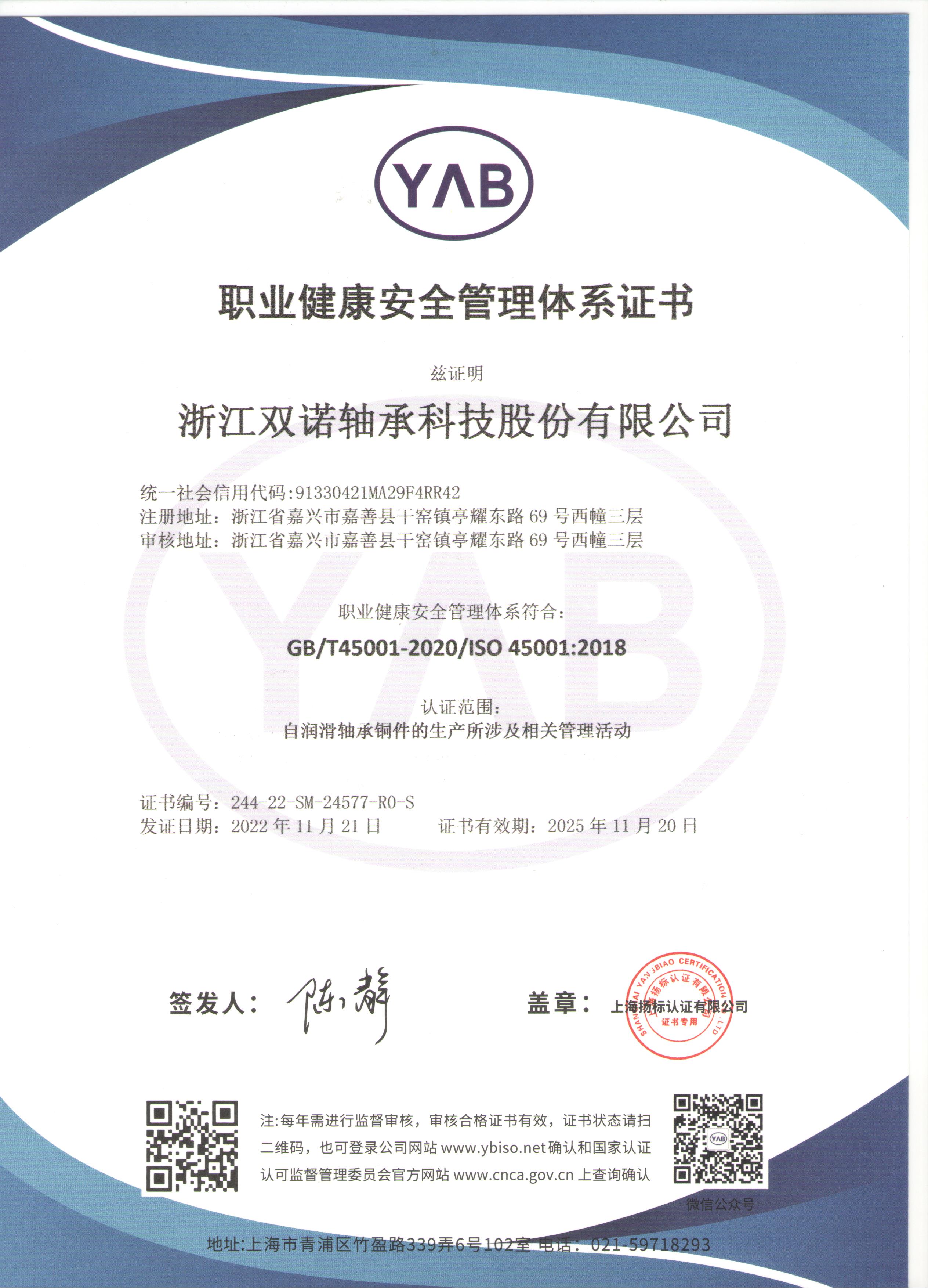
Zhejiang Shuangnuo Technology Co., Ltd. áno Čína JGBF Brass Oilless Ejector Flanged Guide Bearings Bushings dodávateľa a veľkoobchod JGBF Brass Oilless Ejector Flanged Guide Bearings Bushings spoločnosti, Sme profesionálny výrobca rôznych samomazných výrobkov zo zliatiny medi, ktorý využíva procesy ako odstredivé liatie, kontinuálne liatie a odlievanie do kovových foriem. Medzi hlavné produkty patrí mosadz, hliníkový bronz, cínový bronz atď. vyrábané podľa národných štandardných tried. Na tomto základe spracovávame a vyrábame rôzne pevné intarzované samomazné ložiskové produkty. Vyrábame aj bimetalové výrobky a mnoho ďalších druhov výrobkov technológiou spekania. Za takmer desať rokov od svojho vzniku sa spoločnosť zamerala na výskum, vývoj a výrobu rôznych nových samomazných ložísk.

Počas procesu výroby produktov spoločnosť vždy trvá na nezávislom odlievaní a výrobe surovín, aby sa zabezpečila kvalita produktu od zdroja; celý proces odlievania je monitorovaný a hotové výrobky sú trikrát testované spektrometrom pred, v a za pecou, ​​aby sa potvrdilo materiálové zloženie výrobku. Spoločnosť pravidelne poveruje národné testovacie inštitúcie testovaním materiálového zloženia a mechanických vlastností svojich produktov a zákazníkom, ktorí to potrebujú, môže poskytnúť autoritatívne správy o testoch. Spoločnosť implementuje integrovanú výrobu od materiálu po spracovanie hotového výrobku a má viac ako 80 hlavných zariadení, ako sú pokročilé CNC obrábacie stroje, CNC sústruhy a obrábacie centrá. Silná výrobná kapacita zabezpečuje, že výroba materiálu môže byť zorganizovaná pre zákazníkov čo najskôr, čím sa skracuje výrobný cyklus.

  • 0+
    Založenie

    Shuangnuo bola založená v roku 2014 a má 10 rokov skúseností v tomto odvetví.

  • 0+
    Pokročilé vybavenie

    Silná výrobná kapacita zaisťuje, že dokážeme zorganizovať výrobu materiálu pre zákazníkov čo najrýchlejšie a skrátiť výrobný cyklus.
  • 0+
    Spokojnosť zákazníkov

    Máme viac ako 5 000 spolupracujúcich zákazníkov po celom svete.

Naše novinky //
Správy a štatistiky.
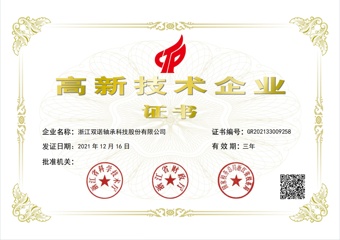
Naša česť //
česť.
Zhejiang Shuangnuo Technology Co., Ltd.
Prísna kontrola kvality //
Pri výbere produktov sa zamerajte na kvalitu.
Zamerajte sa na každý proces, aby ste vytvorili vysokokvalitné produkty.
Sme si plne vedomí toho, že iba poskytovaním vysokokvalitných produktov môžeme uspokojiť potreby našich zákazníkov a vybudovať si dobrú povesť a dôveryhodnosť.

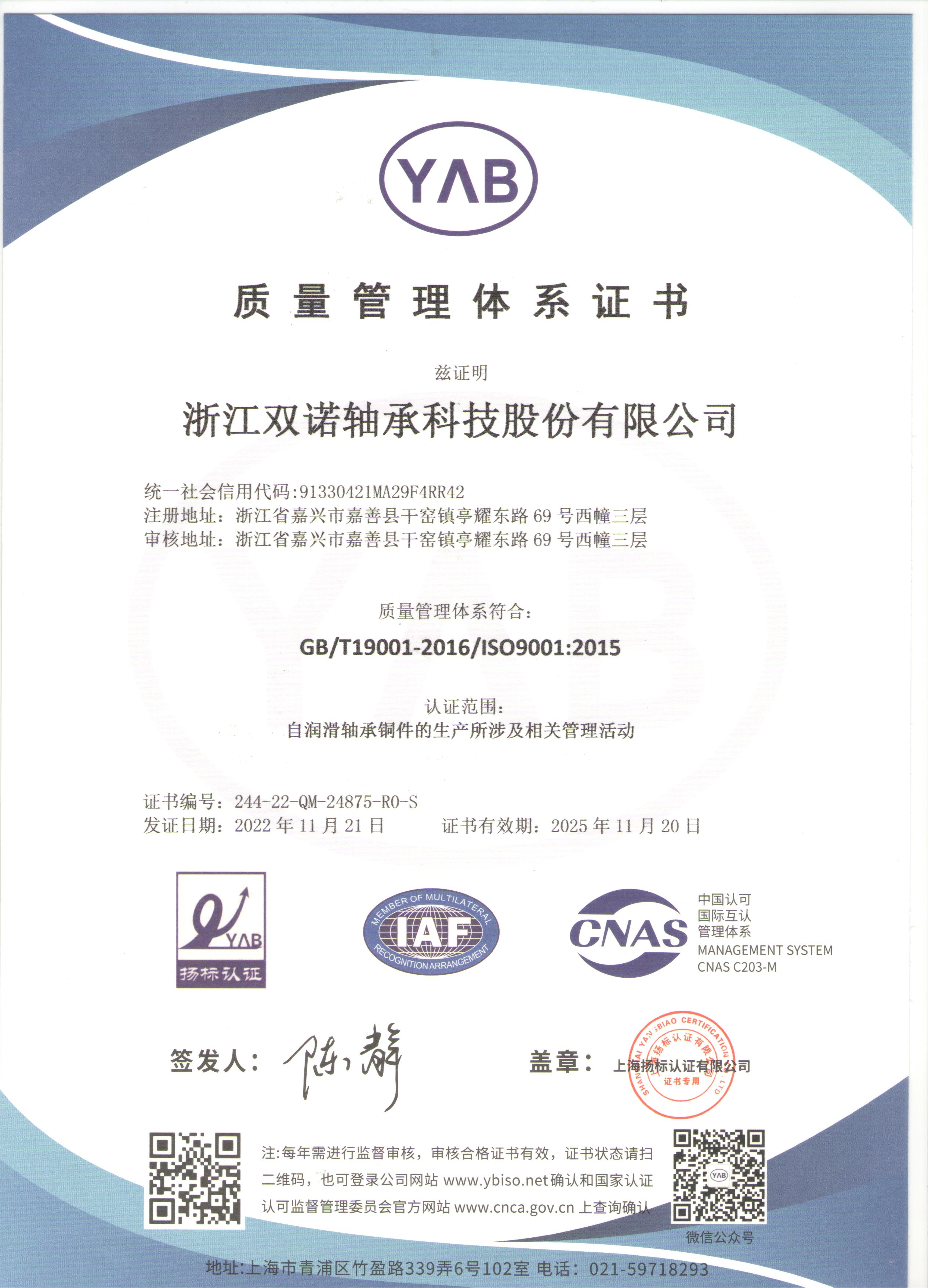
Požadujeme, aby samomazné výrobky zo zliatiny medi spĺňali príslušné národné normy a predpisy. Budeme prísne dodržiavať národné normy kontroly kvality, aby sme zabezpečili, že každý nami dodávaný produkt spĺňa požiadavky na kvalitu a podstúpi potrebné testovacie a certifikačné postupy.